Preparing Your Forge and Forging the Blade
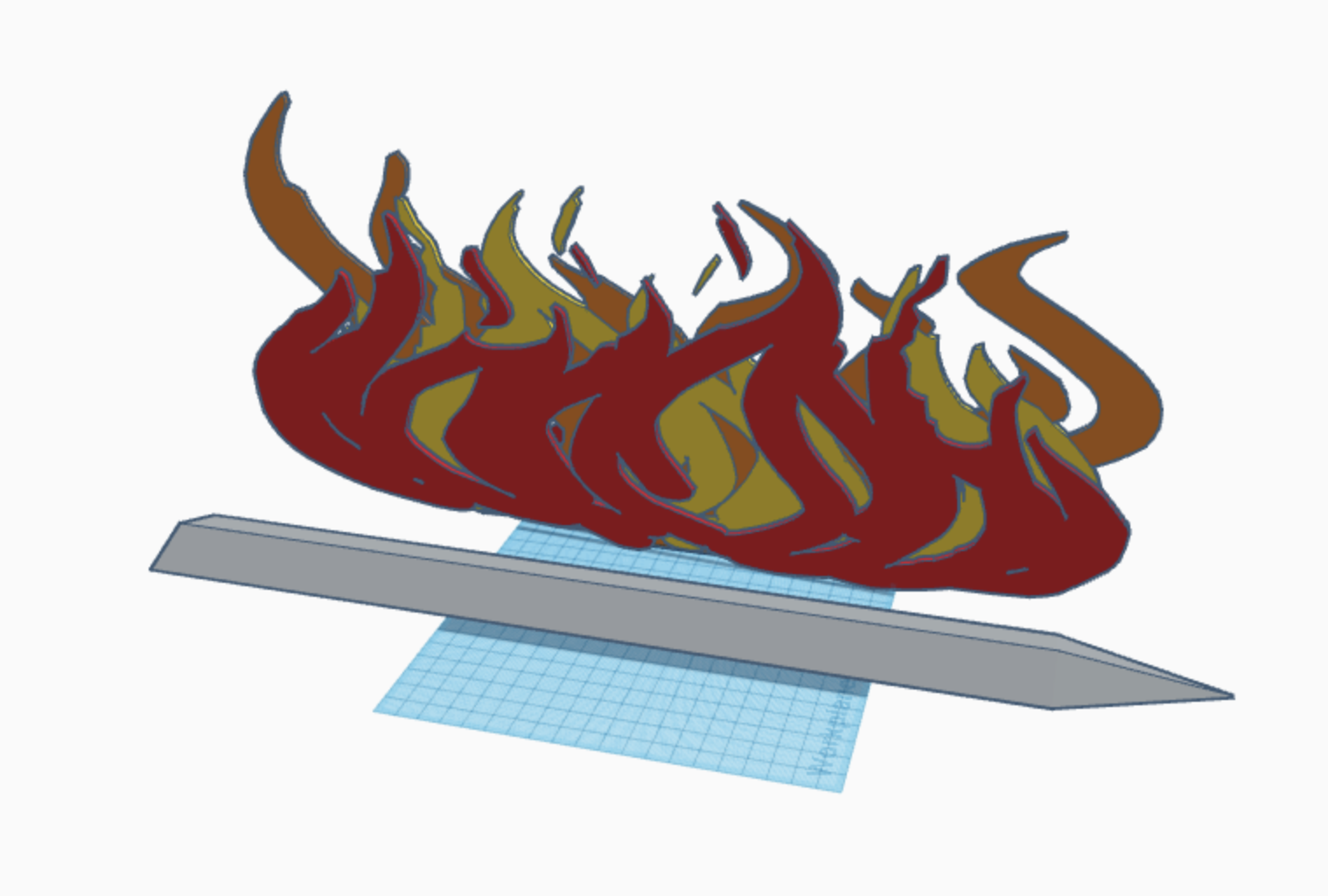
(3D Modeled fire credits to Thiên Huỳnh Quốc)
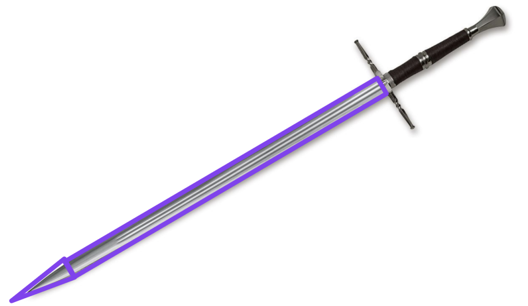
(A sample completed sword blade, made with no details so you can customize it all!)
Outline:
- An Introduction to Smithing (what is CAD?)
- Enter The Virtual Forge (setting up TinkerCAD in your browser)
- Navigating Your Workshop (using the TinkerCAD dashboard)
- Learning the Ways of the Craft (Navigating the Tools)
- The World of Magic (using TinkerCAD shortcuts)
- Forging by Parts (learning to use the shapes sidebar)
- The Body of the Blade (creating the long part of the blade)
- Forging the Blade (but actually this time) (making the bone of your sword)
- Sharpening the Tip (creating the top of the blade)
- (Optional) A Guide to the Elements (3D filetype guide)
A Handout
Here 's a one-page handout that includes a lot of the most important functions that you'll need to remember, and also includes all of the really helpful keyboard shortcuts! Make sure you at least take a look at it! It will be very helpful later!
An Introduction to Smithing: So what's CAD, and why CAD?
(TLDR at the bottom because I know this is kinda long)
What is CAD?
CAD (Computer Aided Design) is the use of computers to help design (wow never would have guessed).
More specifically, it's software that replaces normal tools like pencil and paper. Instead of being forced to draw thousands of technical drawings using tools like rulers and compasses, and even then being slightly imprecise, a CAD software cuts that all out because its lines are always straight, and it can simulate things like rotations, interactions between parts, or even the physics of systems. For instance, if the design was for a house, the architect and simulate and find stress on different portions of the house, and reinforce the parts that need strength.
CAD can be split into two major types: 2D CAD and 3D CAD.
2D CAD
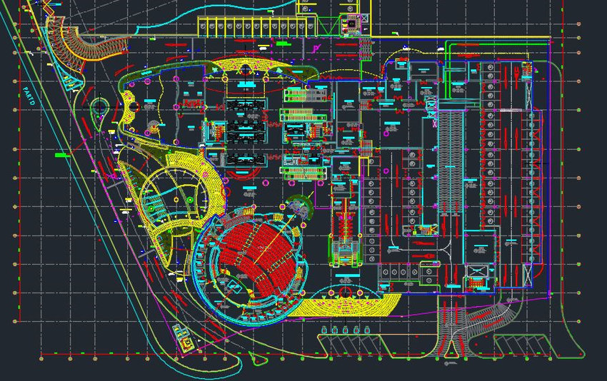
(Barki, Hichem & Fadli, Fodil & Shaat, Ahmed & Boguslawski, Pawel & Mahdjoubi, Lamine. (2015). BIM Models Generation From 2D CAD Drawings And 3D Scans: An Analysis Of Challenges And Opportunities For AEC Practitioners. 10.2495/BIM150311.)
2D CAD programs usually are used for simpler things like fashion, floor plans, and application layouts. These are usually used for either very simple things or digital things that do not need to be made into 3D. It's not much different from blueprints, if they are used for 3D things. The image above is a particularly complicated floor plan, made with 2D CAD.
3D CAD
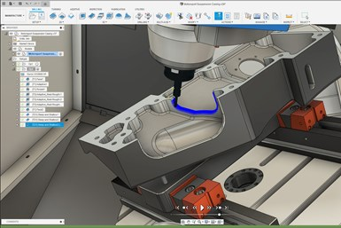
(Osborne, Angela, 6-21-2022, "Autodesk Fusion 360 Unifies Design, Manufacturing Process," Production Machining, https://www.productionmachining.com/products/autodesk-fusion-360-unifies-design-manufacturing-process)
3D CAD, on the other hand, is used far more widely. For instance, it can be used to replace blueprints. Instead of being forced to draw blueprints of every perspective, you can just look around in the simulated world of 3D CAD. The above is an application in engineering.
CAD in Industry
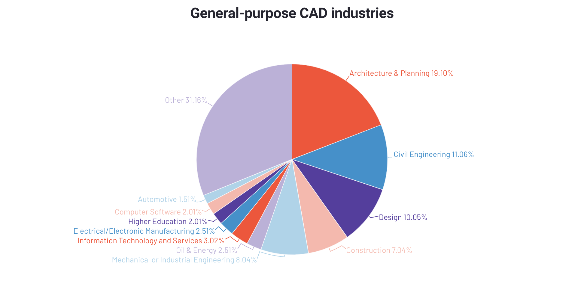
(Michael Gigante, 7-15-2020, "Computer-Aided Design (CAD): State of Category," G2, https://www.g2.com/articles/computer-aided-design-cad-state-of-category) ^ Provides a lot of cool insights about uses of CAD in the Market today
These are some of CAD's applications to Industry. Learning this can open up whole new career paths to you! Even in other industries, CAD can help you visualize things.
What will I learn?
Beyond just skills with CAD design, it also provides many useful exercises to the brain. It encourages you to see many items not as base items, but as a combination (or a difference) of many different shapes. It can also help develop your visualization skills.
3D CAD (think of it like a really advanced weapon blueprint planner) is what we will be using to make the swords! TinkerCAD has multiple applications, but its first (and most common) use is in 3D modeling, with basic shapes.
TL; DR: CAD (Computer Aided Design) is using computers to help in designing things, that are either 2D (flat) like clothes or 3D (not flat) like buildings or robots. It's got a lot of uses in industry and design. In this jam, you will learn how to make simple items like swords in TinkerCAD, an online CAD software.
With that out of the way (and you hopefully more and more interested in CAD Design), let's hop in!
Enter the Virtual Forge
The best option for online CAD is TinkerCAD, a free website CAD made by Autodesk, a big CAD company.
But Before you enter...
Prepare a mouse. TinkerCAD (and most other 3D Modeling programs) are wayyyy easier to use with a mouse, although it is still usable with a trackpad. To prove this point (and totally not because I'm too lazy to get my mouse,) I will make this tutorial example using my trackpad.
Personally, I wouldn't subject anyone to the hell of trackpad CAD, especially in more advanced programs.
Create an Account
Head over to the TinkerCAD Website and create an account
Navigating Your Workshop
Welcome to your TinkerCAD Dashboard!
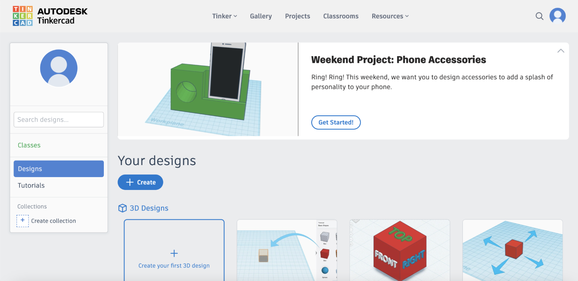
On the left is your profile. Everything here is self explanatory, and Collections is equivalent to folders (or I guess something like an armory to store collections of items).
At the middle-top of the screen you can find many different things. From left to right, they are:
- Tinker: Make a new design
- Gallery: Browse great things others made
- Projects: Tutorials to make projects
- Classrooms: Set up a Google Classroom-esque system
- Resources: Many helpful resources
If you scroll down a bit, you can find the three types of things that TinkerCAD currently allows you to make.
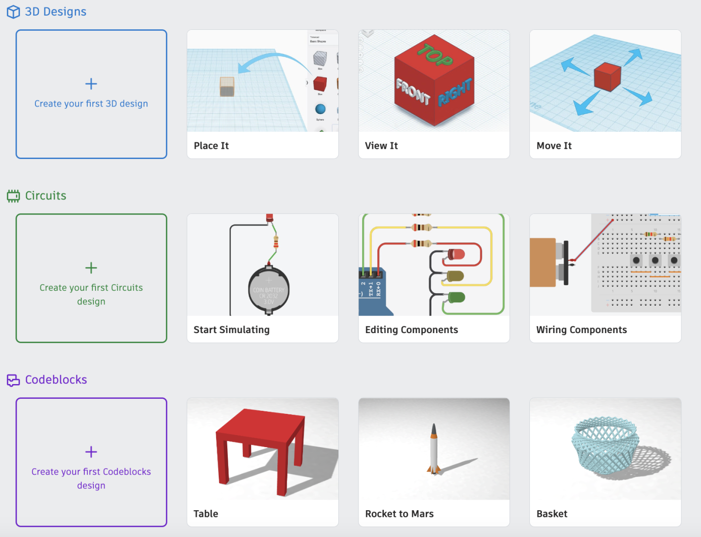
We'll start with the first one, a 3D design. Create a new one, and let's hop in!
Learning the Ways of the Craft
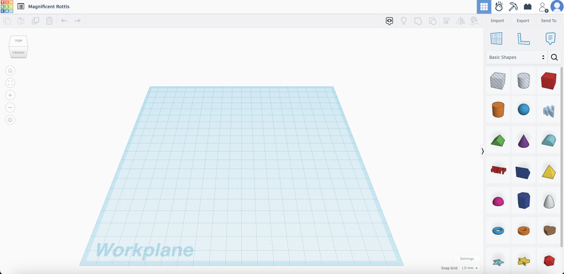
Woah...
Let's break it down into different portions.
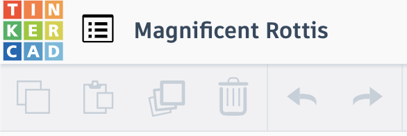
Top Left: Magical Duplication
Did you expect this forge to be realistic, and accurate to the Middle Ages?
NO! Like many fantasy worlds, we have MAGIC to speed up your forging process!
These are your magical tools that do the basic functions for you.
The logo just teleports you back to your dashboard.
The menu button teleports your projects in front of you for quick access.
The random text is a name, which TinkerCAD will randomly generate every time. It's usually just some gibberish, and you should usually rename what the file to what this project is. Just click on it to rename.
... Hey, you can rename this file later. Learn the basics first.
The little buttons are greyed out because you haven't made anything yet. From left to right, they are:
Copy, Paste, Duplicate, Delete, Undo, and Redo.
If you're an experienced magic user, you can always just use the spells: Ctrl C, Ctrl V, Ctrl D, Delete/Backspace, Ctrl Z, Ctrl Y
If you're using the spellbook Mac Book, just use Cmd instead.
Top Right: Magic Simulations

From left to right, they are:
Normal Buildplate (where you are right now) Physics Simulation (throw things at your projects and knock them around) Minecraft Simulation (shows you how to build items in Minecraft) Lego Simulation (shows you how to build items in Lego) Invite Collaborators
Just Below That: Taking it out of the Forge
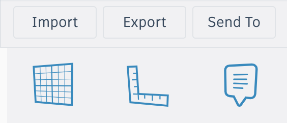
First, the blue buttons below let you create workplanes, rulers, and notes.
The buttons above bring up new panels where you can import and export your models. Read the guide about filetypes at the bottom for more information about those.
Below this is the gallery of shapes, and to the right are additional tools. We will go over both of those in Part 1.
The Workplane: Your Anvil
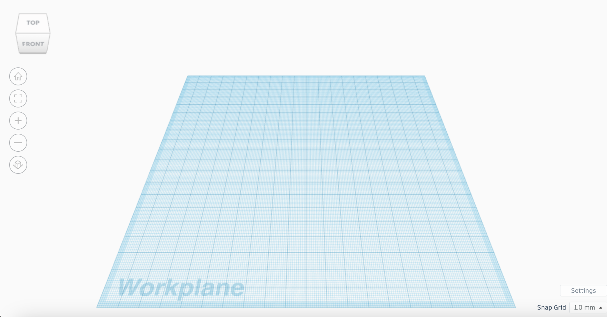
Finally we get to the biggest thing on the screen. This is where all of your items are going to go.
The top cube thing is the viewing cube. Drag that around or use right click drag to change the angle at which you view your weapon. Next, from top to bottom is Home, Full screen, Zoom in, Zoom out, View change.
And with that we are done! Worried you will forget something? Just hover over anything to read the tooltip!
The World of Magic
Did you think moving your cursor all the way to a button to click it took way too long? Don't worry! The person who made your forge (TinkerCAD's developers) left you a handy list of all the spells (shortcuts) that people use!

(Team Tinkercad, 06-25-2019, "Keyboard Shortcuts for the 3D Editor," https://www.tinkercad.com/blog/keyboard-shortcuts-for-the-3d-editor)
This should also be in your Handouts page!
Forging by Parts:
TinkerCAD's assistants already made the base materials for our sword, so that you (the master blacksmith) won't need to concern yourself with the basics.
Remember the shapes panel to the very right? Now we are going to introduce that.
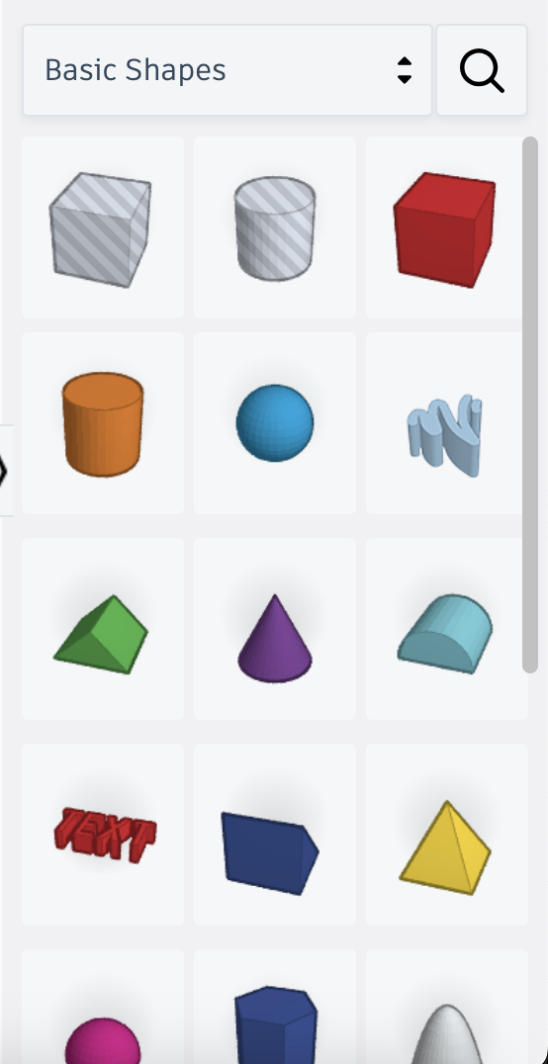
This side panel shows you all the shapes for your project. These basic shapes let you create the basic parts of your model from common polyhedrons, and there are many shapes that others have made already, which you can find by expanding the drop-down bar and clicking on another collection.
Alright, now let's place a cube into the workspace. Drag the red cube onto the workplane (or just click twice). A small menu should pop up:
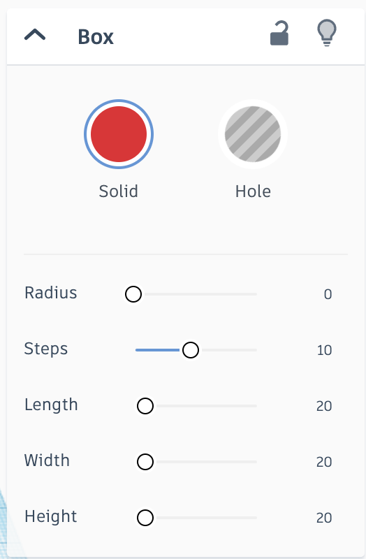
These are the shape's Attributes. Each shape has its own unique attributes, but generally all shapes have at least one.
For a cube, the first one indicates the radius of the circle if you wished to round it. The second one is largely specific to round shapes, and just indicates how smooth you want it to be, with more steps being more smooth, while the last 3 are self-explanatory.
If you are ever confused about attributes, just experiment with it!
We will address what Solid and Hole means in part 2! We will explore that in part 2!
The Body of the Blade
As a 3D Modeler (or Blacksmith, however you prefer to call yourself), you need to practice the skill of generalizing an object into its basic, regular polyhedron pieces. Or in other words, you have to break an object up into its basic shapes (if you are an artist, it's like breaking an animal's leg into quadrilaterals for easier drawing).
(Administrator, 12-6-2020, "Week Starting 7th December," Space Aylesbury, https://www.spaceaylesbury.org/week-starting-7th-december-breaking-down-a-drawing-into-shapes-part-1/)
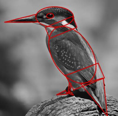
We will practice this on the blade. Let's look at how a sword's blade usually looks (along with my terrible drawing).
(Militarysurplusworld.Com Based On Idosell, n.d., "Ferrum sword -Magnum," militarysurplusworld, https://www.militarysurplusworld.com/product-eng-43263-Ferrum-sword-Magnum.html)
Looks like a long, almost rectangular shape, with a triangle attached to the end.
And let's also look at the cross-section.
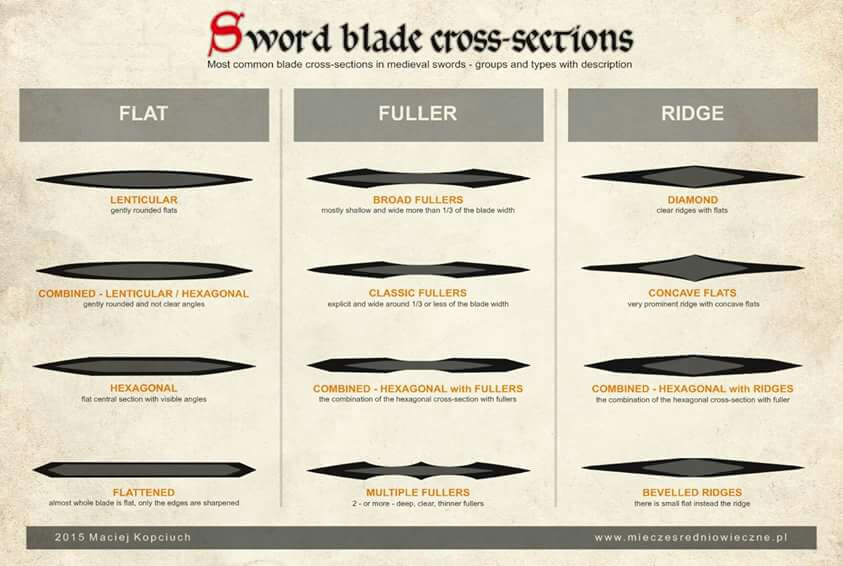
(Starr Z. Davies, n.d., "Wednesday Warriors," https://starrzdavies.com/wednesday-warriors-3-basic-blade-cross-sections-and-their-purpose/)
Let's just use a simple diamond shape right now. It looks like, well, a diamond.
So (QUIZ TIME!!!) what kind of 3D shape do we need for the long, straight part of the blade? (Also, it's really hard to describe what I'm talking about. Let's just call the long, straight part of the blade the "stem" for now.)
Great! That about the top, pointy part?
Now that we have that, all we need is to actually make it.
Forging the Blade (but actually this time)
If at any point in this section you get confused, there are demo videos in the slides up top!
Now we will make the bone of your sword.
You may have realized that, although we figured out we needed a rhombus, TinkerCAD doesn't actually have rhombus as a base shape. How do we make it then?
Let me tell you the ways of the 3D Modeling Blacksmith. There's 3 ways to make any shape:
- Combine a few shapes (Addition)
- Subtract shapes from each other (Subtraction)
- Deform another shape to make what you want (Modification)
Let's take a look at the sidebar again, and cross out everything that doesn't look even remotely workable. We need sharp edges, right? We can cross out all the rounded shapes.
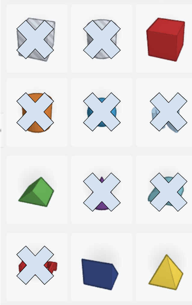
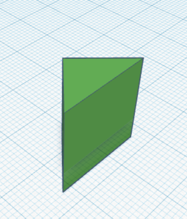
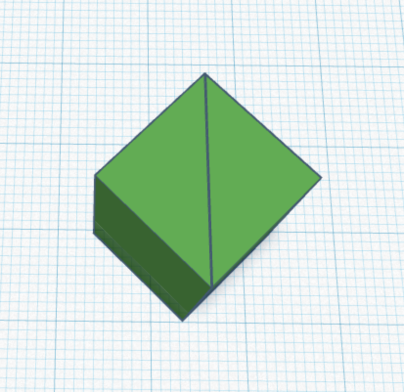
Let's go through our options and try each one. First is addition. We know that we want a rhombus shape, and a rhombus is basically just two triangles. The green triangular prism seems up to the job. Let's drag it onto the workplane.
Oh right, let me tell you the basic controls. Click to select, Hold right click and drag to change perspective, and scroll to zoom. Press shift while dragging with right click to slide your perspective. If you want to return to a cardinal direction, just click a face, edge, or vertex of the little cube at the top left.
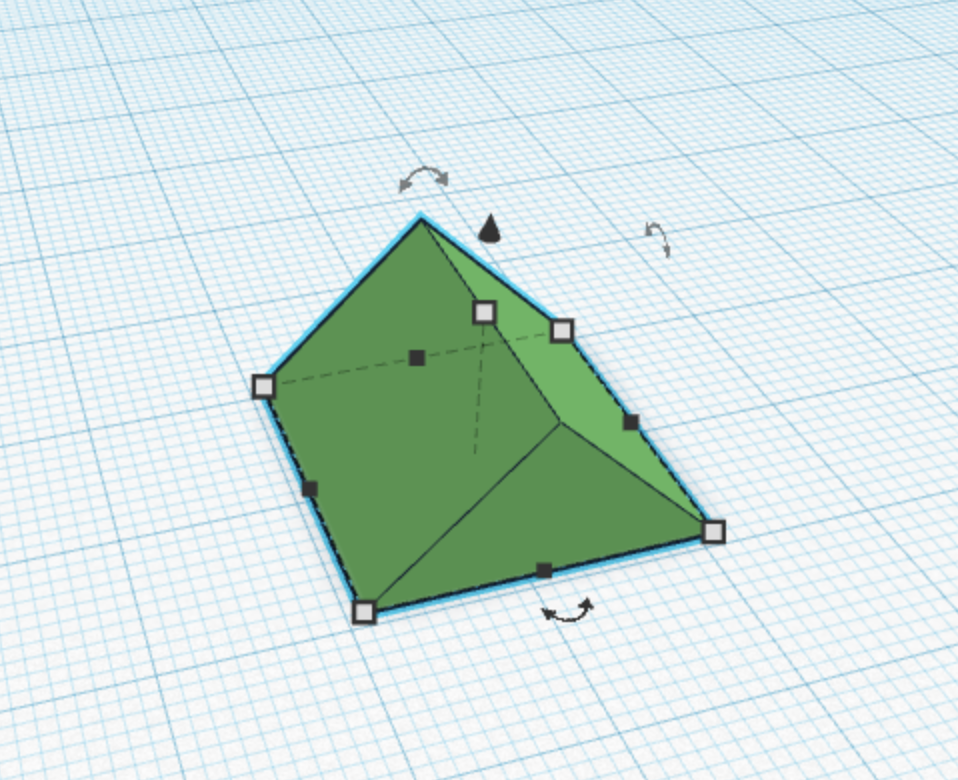
The blue highlight shows what you are clicking, the white squares at the bottom allow you to modify the length and width when you drag it, and the black dots only change one dimension if you want to (for instance) lock the width and only modify the length. The top white dot also lets you only modify the height.
You can drag a shape to move it around, drag the top black arrow to move it up, and press the key "d" to drop any floating shape down (or up) to the workplane.
The three arrow things indicate rotations. We will be using that now.
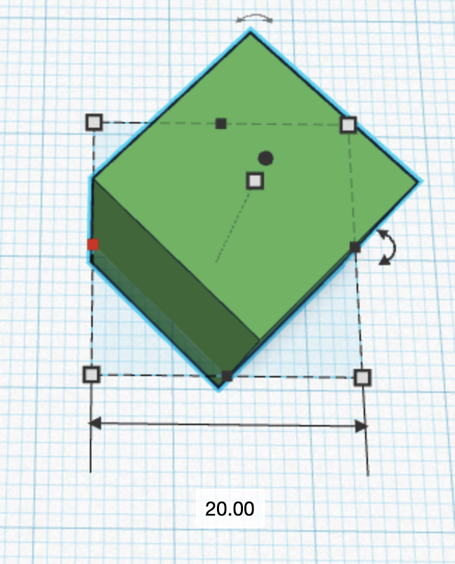
We want to rotate this so it stands upright. Click and hole on the little rotation button you see on the top right (you may want to change perspectives, since if you are just looking at the front you won't see it)
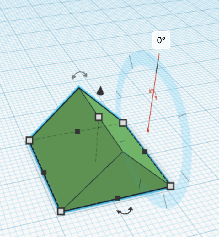
Now a ring will pop up. Drag it around the ring, but hold it over the bigger inside ticks instead of the smaller outside ticks. Doing this makes your shape snap to 45 degree increments instead of making it less precise.
Great! It's upright! We'll need another prism, so just go ahead and make another one, but rotate it the other way. You can also drag the shape to move it around
Now let's align and merge.
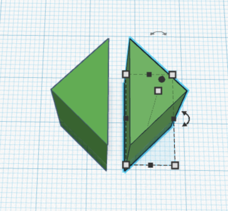
Move it until it's roughly touching. The line between them will be very thin.
Next, hold shift and select both shapes. Look to the top right, the group symbol should light up.
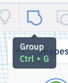
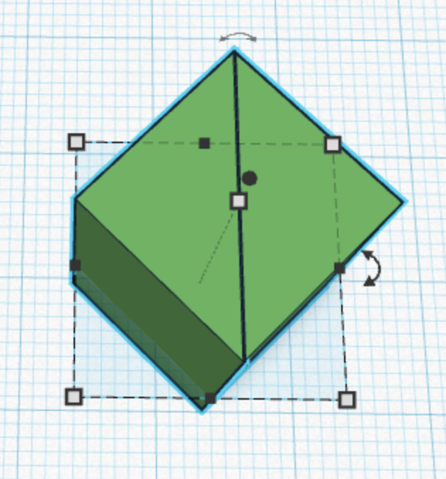
Click it and after a while, the line between should dissapear. You've grouped a shape!
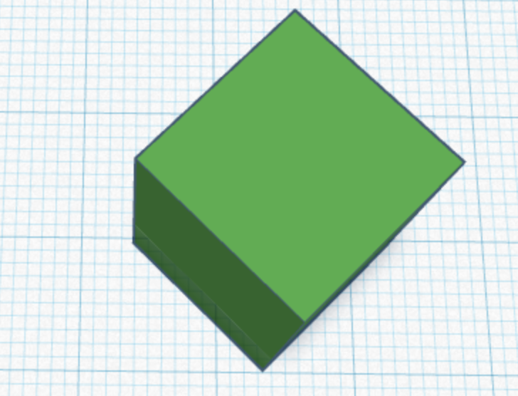
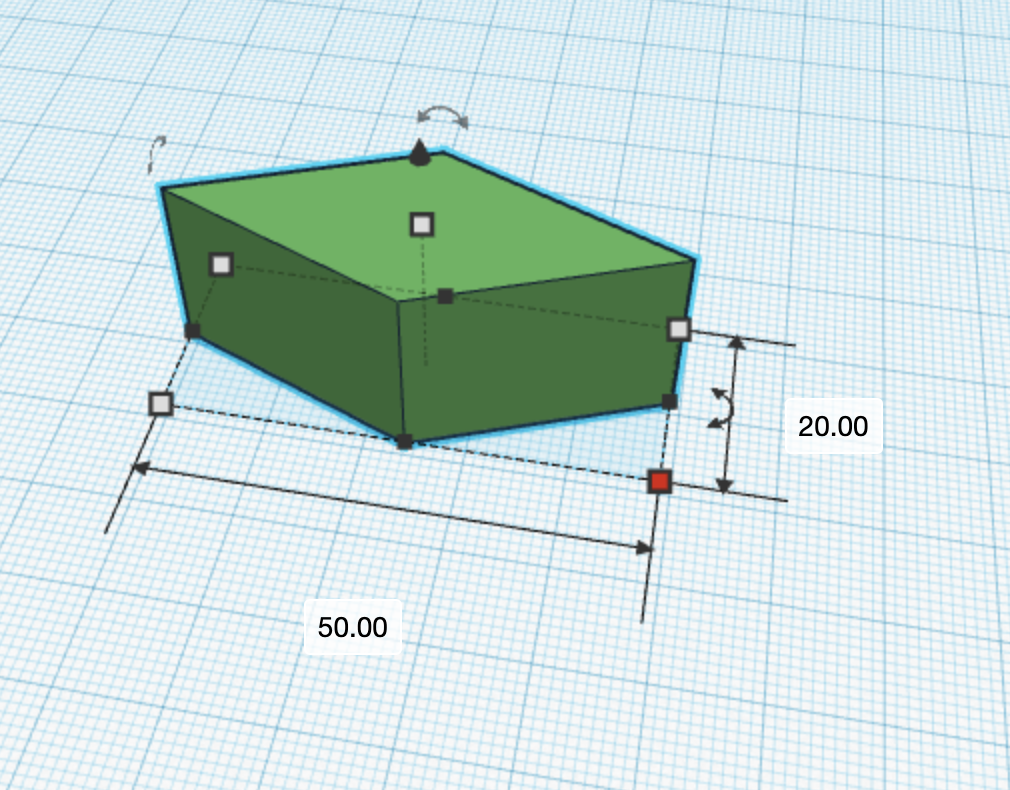
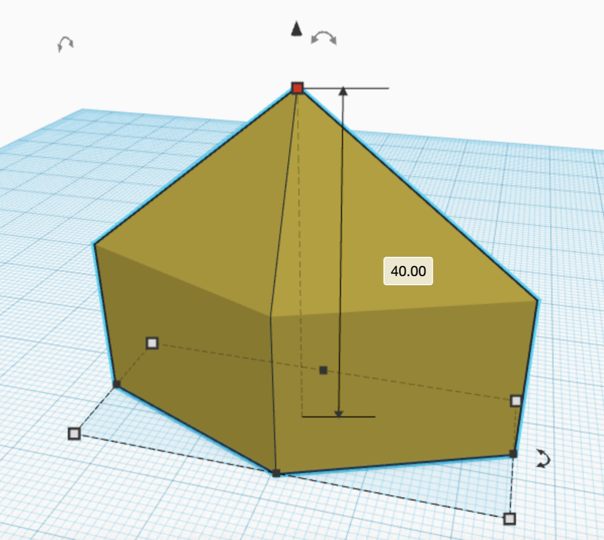
Now just stretch it a bit with the little black dot at the bottom.
The number indicates now long in millimeters it is. Click and type into it to indicate a length if you would like, or just drag the black dot that should have just turned red.

Great! That's one way of forging the stem. The other way, using the modification technique, will be left as an exercise to the reader (always wanted to say that)
Now, just drag the top white dot upwards, and you now have a long blade! For now though, since we need a tip, let's keep it the same length.
Sharpening the Tip
Remember the dimensions of the bottom? Just click on a white dot to check.
20 mm by 50 mm. Let's now make the tip. Let's also go a bit faster now that you've learn the basics.
Drag a yellow pyramid onto the plane, and rotate it 45 degrees to align with the blade.
Edit its dimensions to match with the base.
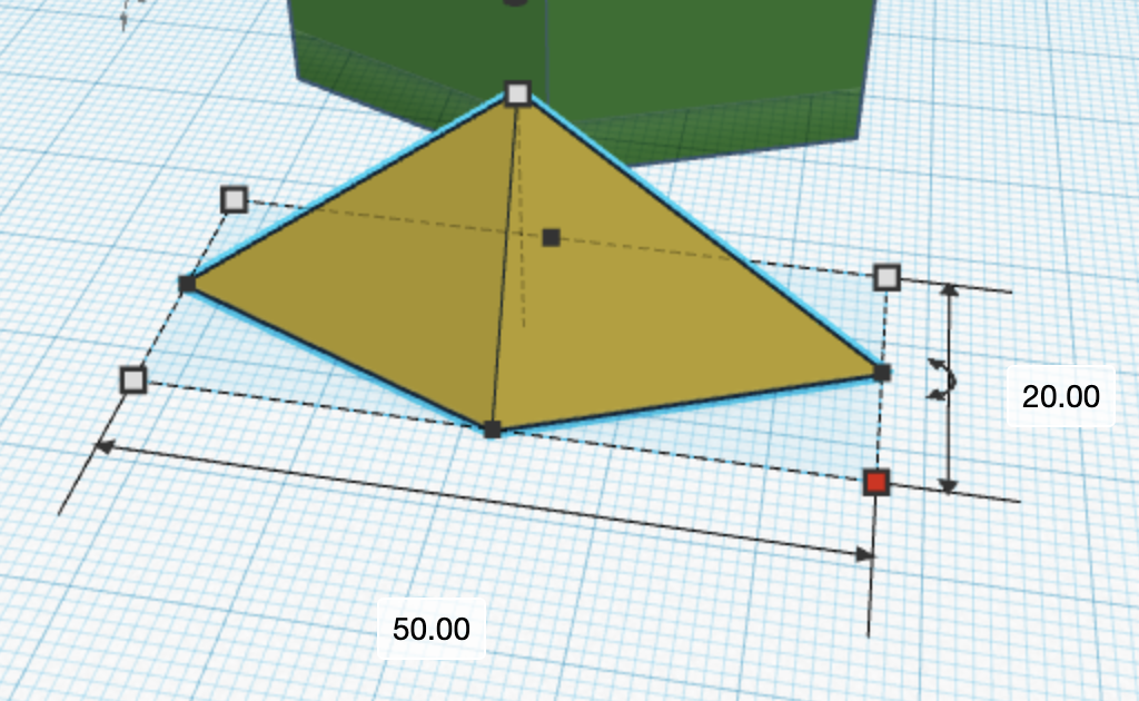
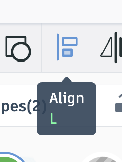
Let's use a neat little tool called align. select both shapes with shift, now click this new button on the top right.
Black dots should pop up. Each one aligns the shapes in a different dimension. We are interested in the ones in the middle of the base.
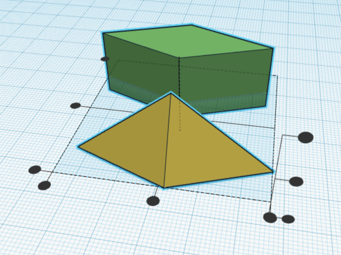
You should get this.
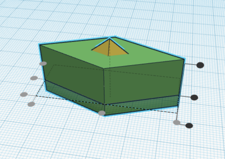
Press "d" to situate it on the workplane, and drag the pyramid up using the arrow until it aligns with the base, much like we did earlier with the two green triangles.
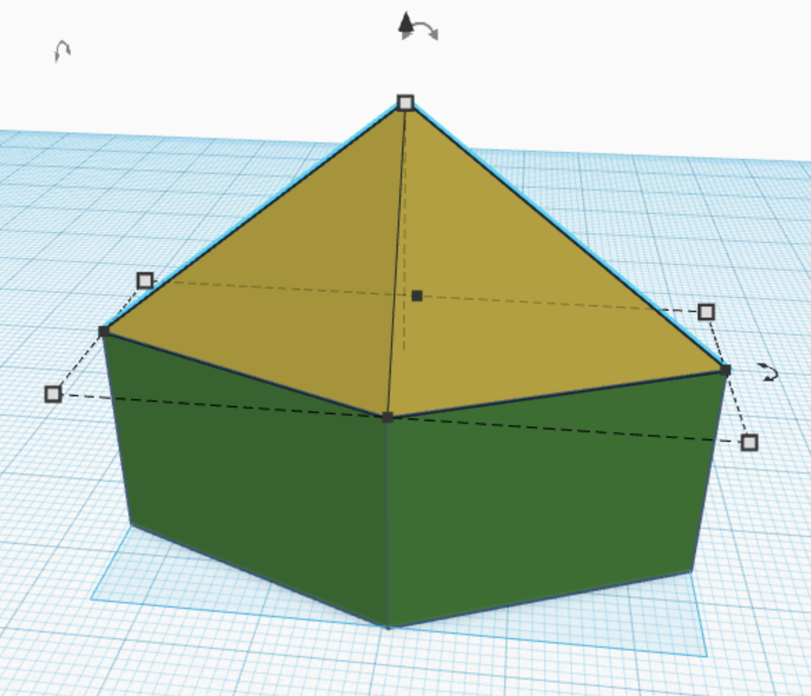
Group them together, and you have a short blade!
Don't worry if it changed entirely to yellow or green, TinkerCAD assigns colors based on its parts to the grouped whole. just click on it, and then this in the sidebar to change color if you would like.
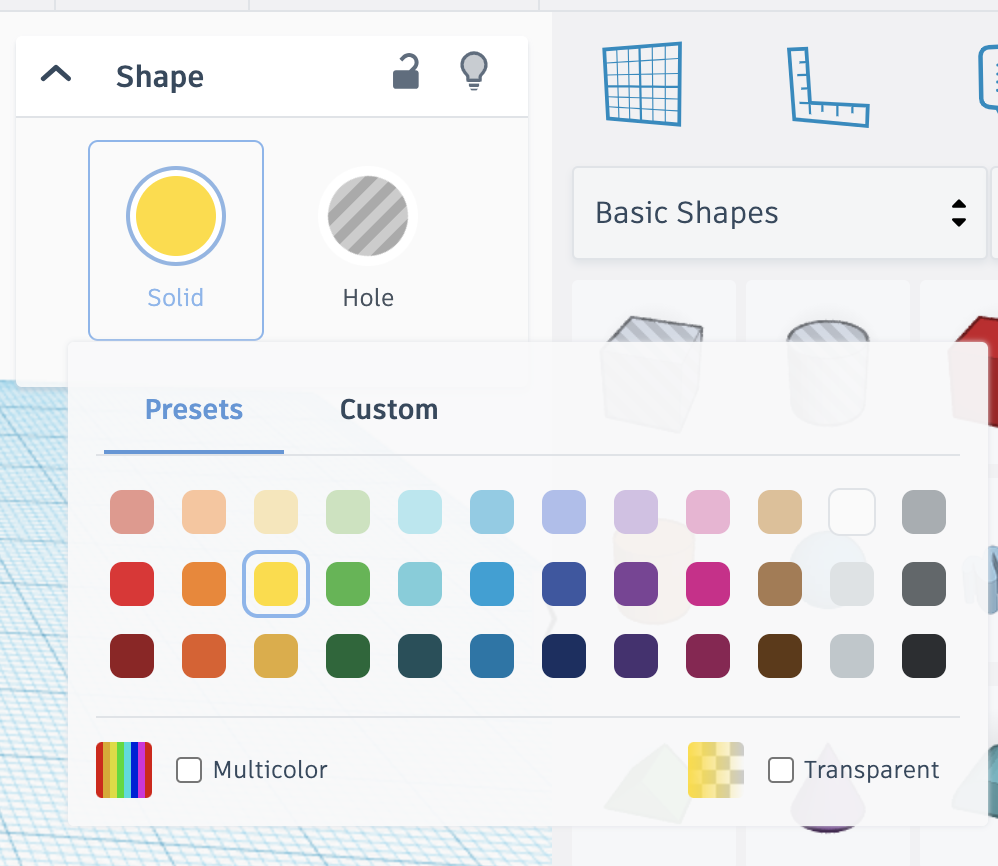
To lengthen the blade, let's drag the top white dot upwards, but not before zooming out first so we have more space.
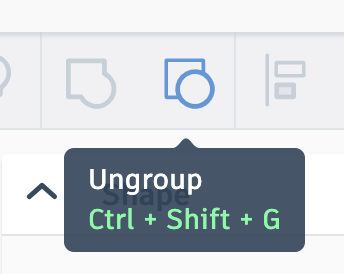
Feel free to click this button and ungroup to resize the stem and tip individually.
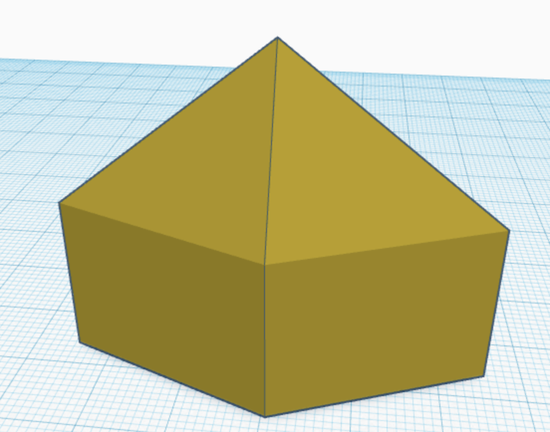
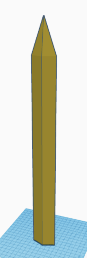
Great! You now have a blade of the legends!!!
(Optional) A Guide to the Elements
You should read this section if you have a 3D Printer, or if you plan to bring your creation to the real world in some way!
There are many different elements (or as most people call it, filetypes) you can use to create your projects.
3D Filetypes
.obj files are supported by a lot of 3D printers and programs. In addition to shape, it stores color, texture, and material information. The downside is that obj files do not track the size, making precise projects hard.
.stl files are the most common types used for 3D programs. Most 3D printers also support it. Generally, default to using this file. However, it still does not track size.
Although TinkerCAD does not export into .3mf files, it's also very common and is arguably the best filetype. The reason is simple: it tracks size.
2D Filetypes
.svg files store a 2D pattern as vectors, which tells machines like computers how to render it, and machines like Laser Cutters and CNC machines how to cut it from wood or metal.
Summary and Next Up:
Thanks for choosing this Jam and for choosing the wonderful world of 3D modeling! With these skills, you can soon interact with your software in the real world!
Today, you learned how to Navigate TinkerCAD, Use its tools, and Think like a CAD designer!
On the next episode/step we will finish the sword by creating the hilt!
See you next time!
Congratulations! 🎉 🎉 🎉If you're a highschooler who enjoys programming or tinkering with hardware, make sure to join Hack Club, the world's largest nonprofit empowering teenagers to make cool projects! There's tons of programs where you can get prizes for programming, get your hardware projects fully funded and you can join the awesome community of 100k+ teenagers who love making cool stuff (just like you!).